- 您现在的位置:买卖IC网 > Sheet目录2001 > ISL12058IUZ (Intersil)IC RTC/CALENDAR I2C-BUS 8-MSOP
17
FN6756.0
June 15, 2009
ISL12058
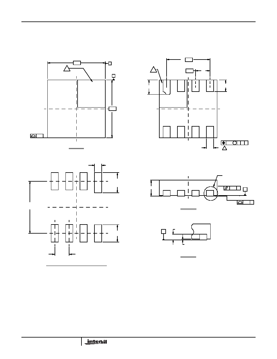
Package Outline Drawing
L8.2x2
8 Lead Ultra Thin Dual Flat No-Lead COL Plastic Package (UTDFN COL)
Rev 3, 11/07
TYPICAL RECOMMENDED LAND PATTERN
DETAIL "X"
TOP VIEW
BOTTOM VIEW
SIDE VIEW
located within the zone indicated. The pin #1 identifier may be
Unless otherwise specified, tolerance : Decimal ± 0.05
Tiebar shown (if present) is a non-functional feature.
The configuration of the pin #1 identifier is optional, but must be
between 0.15mm and 0.30mm from the terminal tip.
Dimension b applies to the metallized terminal and is measured
Dimensions in (
) for Reference Only.
Dimensioning and tolerancing conform to AMSE Y14.5m-1994.
6.
either a mold or mark feature.
3.
5.
4.
2.
Dimensions are in millimeters.
1.
NOTES:
2.00
7X 0.4 ± 0.1
0.15
( 1 . 8 )
(4X)
( 8X 0 . 25 )
( 1X 0 .70 )
( 6X 0 . 5 )
0 . 55 MAX
BASE PLANE
C
SEATING PLANE
0.08
C
0.10
C
0.25 +0.05 / -0.07
SEE DETAIL "X"
0.10
4
CA
MB
INDEX AREA
6
PIN 1
2.00
A
B
PIN #1 INDEX AREA
0.50
2X 1.5
6X
6
( 7X 0 . 60 )
0 . 00 MIN.
0 . 05 MAX.
C
0 . 2 REF
5
4
8
1
1X 0.5 ±0.1
发布紧急采购,3分钟左右您将得到回复。
相关PDF资料
ISL12059IBZ
IC RTC/CALENDAR I2C-BUS 8-SOIC
ISL12082IUZ
IC RTC I2C LO-POWER 10-MSOP
ISL1208IU8-TK
IC RTC/CALENDAR I2C 8-MSOP
ISL1209IU10-TK
IC RTC/CALENDAR I2C 10-MSOP
ISL1218IUZ
IC RTC LP BATT BACKED SRAM 8MSOP
ISL1219IUZ-T
IC RTC LP BATT BACK SRAM 10MSOP
ISL1220IUZ
IC RTC LP BATT BACK SRAM 10MSOP
ISL1221IUZ
IC RTC LP BATT BACK SRAM 10MSOP
相关代理商/技术参数
ISL12058IUZ-T
功能描述:实时时钟 REAL TIME CLK W/ ALARM & TIMR FUNCTNS RoHS:否 制造商:Microchip Technology 功能:Clock, Calendar. Alarm RTC 总线接口:I2C 日期格式:DW:DM:M:Y 时间格式:HH:MM:SS RTC 存储容量:64 B 电源电压-最大:5.5 V 电源电压-最小:1.8 V 最大工作温度:+ 85 C 最小工作温度: 安装风格:Through Hole 封装 / 箱体:PDIP-8 封装:Tube
ISL12059
制造商:INTERSIL 制造商全称:Intersil Corporation 功能描述:Low Cost and Low Power I2C Bus? Real Time Clock/Calendar
ISL12059IBZ
功能描述:实时时钟 REAL TIME CLK W/ ALARM & TIMR FUNCTNS RoHS:否 制造商:Microchip Technology 功能:Clock, Calendar. Alarm RTC 总线接口:I2C 日期格式:DW:DM:M:Y 时间格式:HH:MM:SS RTC 存储容量:64 B 电源电压-最大:5.5 V 电源电压-最小:1.8 V 最大工作温度:+ 85 C 最小工作温度: 安装风格:Through Hole 封装 / 箱体:PDIP-8 封装:Tube
ISL12059IBZ-T
功能描述:实时时钟 REAL TIME CLK W/ ALARM & TIMR FUNCTNS RoHS:否 制造商:Microchip Technology 功能:Clock, Calendar. Alarm RTC 总线接口:I2C 日期格式:DW:DM:M:Y 时间格式:HH:MM:SS RTC 存储容量:64 B 电源电压-最大:5.5 V 电源电压-最小:1.8 V 最大工作温度:+ 85 C 最小工作温度: 安装风格:Through Hole 封装 / 箱体:PDIP-8 封装:Tube
ISL1208
制造商:INTERSIL 制造商全称:Intersil Corporation 功能描述:Low Power RTC with Battery Backed
SRAM
ISL1208_06
制造商:INTERSIL 制造商全称:Intersil Corporation 功能描述:Low Power RTC with Battery Backed SRAM
ISL12082
制造商:INTERSIL 制造商全称:Intersil Corporation 功能描述:I2C-Bus? Real Time Clock with Two Interrupts, Alarm, and Timer
ISL12082IB8Z
功能描述:实时时钟 LW PWR RTC W/ALARM & TIMR FUNCTIONS 8LD RoHS:否 制造商:Microchip Technology 功能:Clock, Calendar. Alarm RTC 总线接口:I2C 日期格式:DW:DM:M:Y 时间格式:HH:MM:SS RTC 存储容量:64 B 电源电压-最大:5.5 V 电源电压-最小:1.8 V 最大工作温度:+ 85 C 最小工作温度: 安装风格:Through Hole 封装 / 箱体:PDIP-8 封装:Tube